[JC Home]
Electric Field Mill Fabrication
Jim Campbell
This page describes the construction of an electric
field mill. This is a device to measure the electric
field strength on earth due to the static electric
field and the charge of clouds passing overhead. It
can also be used to investigate static electricity effects.
The body and chopper of the field mill are fabricated from a
4 inch diameter duct fan. The signal conditioning electronics
uses a chopper blade position detector and a synchronous detector
to reduce noise and recover the field sign (positive or negative) as
well as magnitude (strength in V/m).
Photographs:
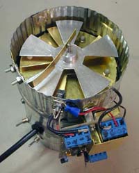
1. Top View
2. Sense Plate Detail
3. Sense Plate Bracket
4. Sense Plate Bracket Detail With Spacer
5. Position Detector Mounting Detail
6. Bottom View
7. Side View
8. Board Backside, Shield Cover Off
9. Board Topside, Shield Cover Off
10. Fan Blades, Before Modification
Figures:
1. Circuit Schematic
2. Plot of Clock and Signal Phase
Web References:
1. Scientific American Amateur Scientist Field Mill Project
2. Scientific American Amateur Scientist Field Mill Project Discussion
3. Lightning Detectors
4. NASA/Marshall Space Flight Center Airborne Electric Field Mill
5. GP-1 Lightning Locator
6. University of Florida Lightning Research Group
7. Experimental E-Field Data
8. Global Atmospherics, Inc.
9. Atmospheric Electricity
HomePage
10. The Earth's Electrical Environment - E.P. Kreider 1986
11. Development of a Lightning Warning System -- Adam Milner
12. Near-real time lightning tracking:
Global Atmospherics, Inc.
13. Intellicast Lighting
14. Lightning strike triggered by a flying airplane
15. Lightningtalks.com
Print References:
1. Martin A. Uman - Lightning, McGraw-Hill Book Company, New
York (1969), 264 pages. Russian translation (1972), revised edition, Dover,
New York (1984). (Available at Borders)
Theory of Operation
The strength of the electric field could be measured, in principle,
by placing a volt meter across plates placed some distance
apart. However, because the meter will have some input
impedance (10 Meg typically), any voltage induced on
the plates will quickly drain away, and would not be
useful for measuring the static field. To make measurements
of the static field, the chopper technique is used. The chopper
blade is arranged over the Sense Plate and rotated so that it
periodically shields, and exposes the Sense Plate to the electric
field. To properly do this, the Rotor must be grounded. The Sense
Plate is grounded through a transconductance amplifier, which
converts the Sense Plate's ground current to a voltage. As the
Sense Plate is exposed to the Field, the field induces ground
currents as it attracts or repels charge from the Sense Plate.
As the plate is shielded from the field, the induced charge drains
away. So the chopper induces an AC ground current which is
proportional to electric field strength.
This AC signal could then be rectified to drive a DC volt
meter or be plotted on a scope. However, by doing this only
the magnitude of the field, not the sign (positive of negative)
would be measured. Also, any noise in the signal would also affect
the output. The signal conditioning for this Field Mill uses a
synchronous demodulation technique to preserve field sign
information and reduce noise.
It works like this: The blade position is measured using an
LED and photo transistor. The Position Sensor clock signal
is used to effectively amplify the AC signal from the Sense
Plate amplifier by either +1 or -1, depending on Rotor blade
position. This has the effect of synchronously rectifying the
AC signal, preserving sign. This rectified signal is then low
pass filtered to remove ripple. Alternatively, this circuit
function can be thought of as the mixing of two identical
frequencies, resulting in output with frequency content at
DC, and twice the input frequency. The low pass filter then
passes only the DC component. This line of thought will also show
how noise at frequencies other that the position clock frequency
are rejected.
Field Mill Fabrication Notes:
Chopper Blades
Get a 4 inch diameter duct fan with fan blades as
shown.
Remove
the fan and break off every other fan blade. Flatten the
remaining blades in a vise.
Housing
I cut a shield from brass and
mounted
it over the motor
too shield the sensor from motor 60 Hz. I don't know how
necessary this really was.
Sensor Plate Mounting Brackets
Cut 3 stripes of brass (about .5 x 2 inches), fold about
in half and drill. Drill three holes so that the
ledge is about 1.5 inches
down from the top. Attach the plastic Sensor Plate hardware
to the brackets and mount the brackets inside the housing as
shown.
Motor Shaft
Drill a hole (the same size at the motor shaft.) clean
through a piece of .5 inch diameter delrin. Drill and
tap the set screws. Cut a piece of stock the same size as the
shaft and mount as
shown
.
Note: My goal was initially
to insolate the chopper rotor, but then found grounding
was required. So you may be able to fabricate the Mill
without having to extend the shaft like this. I did have
to cut the end off the motor shaft to fit the extender
back far enough, and did end up with some wobble on the
extended shaft You could move the whole motor forward as
well if needed.
Sensor plate and Ground Plate
Lay the Chopper blades on a sheet of .015 thick brass.
Trace the outline of the chopper plate using a scribe and
cut it out using tin snipes. Drill the center and cut to
size using a nibble tool. Scribe a circle on a piece of brass
and cut it out. Flatten both pieces (use a tap hammer on a
flat metal surface) and cut out the center hole. Tap the two
pieces together and drill 5 holes around them as shown.
Assemble the sensor plate/ground plate using plastic hardware and
spacers. Transfer the position of the mounting bracket to the
Ground Plate by placing a blob of pink finger nail polish
(thanks Anne) on the
end of each screw and gently setting the Ground Plate down
on it centered. Let the polish dry and drill the three mounting
holes in the
Ground Plate
.
Position Detector
Get a photo interrupter detector as
shown
at The Shack.
Position it right at the edge of the Sense Plate (you may
need to cut a corner off the Sense Plate. Mark it's
position and remove the Rotor and Sense Plate Assembly.
Drill the Position Detector mounting holes and nibble the
center out. Also drill holes for the wires leading to the
Sense Plate Assembly. Mount the Position Detector and
reassemble the Sense Plate and Rotor. Adjust the Rotor
Height so the blades don't hit in the Position Detector.
Check it upside down also, as there is some end play in
the motor shaft.
Rotor Ground
Cut a strip of brass and fold it and mount it as
shown in the
Top View
.
As we expected, grounding the Chopper Rotor proved to be
necessary. When the Rotor is left floating, large static
outputs could be generated by depositing charge on the Rotor.
Grounding the Rotor eliminated this source of offset drift.
Final Assembly
Drill mounting holes for the circuit board and mount it.
Drill hole for off/on switch and mount the Power Supply in
the bottom as
shown in the Bottom View
. Attach the Ground Plate and Case Ground
to the Circuit Board. Attach the Position detector using coax
for the photo transistor output. Attach the Sense Plate using
coax grounded at the Circuit Board. Test.
Circuit Description and Notes
Power Supply
The circuit operates from a split supply (both +8 V and -8 V).
I used a 12 DC wall transformer, a 7808 three pin regulator for
the positive supply, and an ICL7660 voltage converter to generate
the negative supply (or a Linear Tech LT1044 will work, and it is
available in a DIP package from Digikey). You could also just
use a transformer with a center tap an build a positive and negative supply.
Transconductance Amplifier
I used the AD795 as inherited from Shawn Carlson's article,
but really any amp should work since input leakage induced
offsets are blocked by the AC input to the next stage. I also
placed two gain resisters, selectable with a header shorting bar.
The 1 Meg value should give about 6 kV/m output range, which should
be enough for cloud charge measurement. The 100 k value gives about a
60 kV/m output range, and is a better range for static charge investigation
(like measuring the cat). The feedback capacitor values provided a high pass
roll off about 1 kHz. Note: The ICL7660 switches at around 10 kHz,
so rolling off the amplifiers is recommended. The shield around the
first amplifier is also necessary to protect against noise from the position detector.
AC Amplifier Stage
I partitioned the gain into 2 stages of 30 to get an overall voltage gain of
about 1000. This could be done with a single amplifier, but input offset
specifications should be looked into to avoid a large output offset.
The AC coupling corner frequency for each is about 150 Hz, and both
amplifiers are also rolled off at around 1 kHz.
Position Detector Clock Generator
The photo transistor is setup to switch between the positive
and negative supply voltages. This is the level required to
control the 14066 quad analog switch. One of the anolog switch
stages is setup as an inverter to generate a complimentary clock.
Synchronous Demodulator
The output of the AC amplifier is connected to an inverter stage.
Two analog switches are used to alternately apply the inverted,
and non-inverted output to the input of the low pass filter.
The low pass filter is configured with a corner frequency of 7 Hz.
Calibration Amplifier
The output of the low pass filter is applied to a non-inverting
DC amplifier with an adjustable resister in the feed back for
calibration. Calibrate the instrument by placing a sheet of metal
10 cm above the Ground Plate. Put an adjustable power supply
across this plate and the housing ground. Change this applied
voltage from 0 V to 20V (200 V/m field strength) and note output
voltage change. Adjust the resistor until this produces 200 mV
of change (using the 1 Meg resister setting on the first amplifier).
The output voltage sensitivity will then be 1 V / (kV/m). Note:
There will be some level of background field while you do this, so be
sure to note the CHANGE in output while changing the applied field.
Circuit Board Fabrication Notes
Fabricate the
Circuit board as
shown.
Pay careful attention
to
grounding and power distribution. Using terminal blocks
is most helpful during trouble-shooting. It may be helpful
to reposition the Position Detector terminal block further
away from the Sense Plate input terminal block for reasons
discussed below.
Note: Since this circuit has a very sensitive input stage,
and uses synchronous demodulation , it becomes very sensitive
to noise generated by the position detector. The shield around
the first amplifier, and the coax shield on the wire going to the
sense plate are mostly necessary to prevent coupling of the Position
Detector clock signal into the amplifier. I also placed the
photo transistor end of the Photo Detector on top, furthest
from the Sense Plate. The Rotor may also provide some level
of shielding as well. Although there is still some low level
of coupling, these steps brought it under control (<50mV at ac
output). Perhaps I could try wrapping some copper tape around
the photo transistor and grounding it. You can characterize
the level of coupling by observing the AC output signal while
disconnecting the photo transistor at the terminal block.
Before adding the shielding and coax, this test showed several
volts at the AC output!
James A. Campbell
Copyright © 2001
All Rights Reserved
[JC Home]